Posts

Capacitors

Image
By Tim Tolbert In this blog post I would like to explain the overall basics of what Capacitors are, how they work, and how they are made, as I currently understand them to be. A CAPACITOR is a device that stores electrical energy in an Electrostatic Field . The energy is stored in such a way as to oppose any change in Voltage. Inductors oppose any change in Current, while Capacitors oppose any change in Voltage. If two unlike charges are placed on opposite sides of an atom whose outermost electrons (valence electrons) cannot escape their orbits, the orbits of the electrons of the atom are distorted. A simple capacitor consists of two metal plates separated by an insulating material called a dielectric. In the figure below, Part A shows the electrons normal orbits around an atoms proton, for an atom that is suspended between two uncharged bodies (i.e. the uncharged plates of a capacitor): When the two uncharged bodies are charged with opposite charges (such as by being c...

Inductance

Image
By Tim Tolbert In this blog post I would like to explain the overall basics of what Inductance is, and how it is used, as I currently understand it to be. What is Inductance? Inductance is the characteristic of an electrical circuit and/or an electrical conductor that opposes the starting, stopping, or a change in value of current. The symbol for inductance is L and the basic unit of inductance is the HENRY (H). One henry is equal to the inductance required to induce one volt in an inductor by a change of current of one ampere per second. Inductance (the characteristic of opposing change) can be found in non-electrical applications as well. For example, anyone who has ever had to push a heavy load (wheelbarrow, car, furniture, etc...) is aware that it takes more work to start the load moving than it does to keep it moving. Once the load is moving, it is easier to keep the load moving than to stop it again. This is because the load possesses the property of inertia. Inertia is...

Alternating Current - Part 2

Image
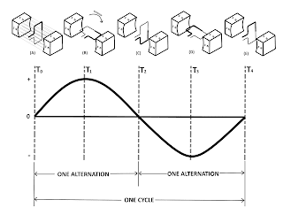
By Tim Tolbert Continued from Alternating Current - Part 1 ... Frequency The number of cycles of AC per second is referred to as the Frequency , and is measured in Hertz. Most AC equipment are rated by frequency as well as by voltage and current. A cycle consists of two complete alternations in a period of time. The term HERTZ (Hz) has been designated to indicate one cycle per second. If one cycle per second is one hertz, then 100 cycles per second are equal to 100 hertz, and so on. In the previous example above, if the loop makes one complete revolution each second, the generator produces one complete cycle of AC during each second (1 Hz). Increasing the number of revolutions to two per second will produce two complete cycles of AC per second (2 Hz). The number of complete cycles of alternating current or voltage completed each second is referred to as the Frequency . Frequency is always measured and expressed in hertz. Alternating-current frequency is an important term to un...

Alternating Current - Part 1

Image
By Tim Tolbert In this blog post I would like to explain the overall basics of what Alternating Current (AC) is, and how it is made and used, as I currently understand it to be. Current that regularly changes direction is called Alternating Current (AC). Alternating current is current which constantly changes in amplitude (value), and which reverses direction at regular intervals (polarity of value). Direct current flows in one direction only, while alternating current is constantly changing in amplitude (value) and direction (polarity). With direct current (DC), current flows only in one direction (from the negative terminal, through the circuit, to the positive terminal), and the amplitude of current is determined by the number of electrons flowing past a point in a circuit in one second. If, for example, a coulomb of electrons moves past a point in a wire in one second and all of the electrons are moving in the same direction, the amplitude of direct current in the wire is one...

Direct Current - Part 3

Image
By Tim Tolbert Continued from Direct Current - Part 2 ... Parallel DC Circuits A Parallel Circuit is defined as a circuit having more than one current path connected to a common voltage source. Therefore parallel circuits must contain at least two or more resistances which are not connected in series. In a parallel circuit, the same voltage is present in each branch (a branch is a section of a circuit that has a complete path for current). The voltage is equal to the applied voltage (E s ), and expressed in equation form as:   E s = E R1 = E R2     Parallel DC Circuit Ohm's law states that the current in a circuit is inversely proportional to the circuit resistance. This fact is true in both series and parallel circuits. There is a single path for current in a series circuit, and the amount of current is determined by the total resistance of the circuit and the applied voltage. In a parallel circuit the source current divides among the available p...